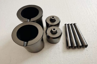
I. Raw Materials
1. Overview
Graphite electrodes and heat exchangers are high-temperature conductive materials produced through a series of processes including mixing, molding, baking, impregnation, graphitization, and machining. Key raw materials:
- Petroleum coke
- Needle coke
- Coal tar pitch (binder)
These materials enable arc furnace steelmaking, where electrical energy is converted into heat (>3,000°C) via electrodes. They are also used in phosphorus, silicon, and abrasive production.
2. Key Raw Materials
(1) Petroleum Coke
A carbon-rich solid byproduct of petroleum refining, classified by:
- Heat treatment:
- Green coke(high volatiles, low strength)
- Calcined coke(processed at 1,250–1,350°C)
- Sulfur content:
- Low-sulfur (<0.5%, preferred for electrodes)
- Medium-sulfur (0.5–1.5%)
- High-sulfur (>1.5%)
(2) Needle Coke
Anisotropic coke with fibrous texture and ultra-low thermal expansion. Critical for:
- High-power (HP) and ultra-high-power (UHP) electrodes
- Low resistivity (≤500 μΩ·m) and high thermal shock resistance
Types: Oil-based(from petroleum) and coal-based (from coal pitch).
(3) Coal Tar Pitch
A viscous binder with:
- Softening points: Low (≤80°C), Medium (80–110°C), High (>110°C)
- Roles:
- Binder pitch: High coking value, β-resin content
- Impregnation pitch: Low QI (quinoline-insoluble), fluidity
II. Manufacturing Process
1. Calcination
- Purpose: Remove volatiles, enhance density/conductivity.
- Equipment: Rotary kilns, shaft furnaces (1,250–1,350°C).
- Quality control:
- Petroleum coke: Density ≥2.07 g/cm³, resistivity ≤550 μΩ·m
- Needle coke: Density ≥2.12 g/cm³, resistivity ≤500 μΩ·m
2. Crushing & Formulation
- Particle sizing: Jaw/roller crushers (0.5–20 mm), ball mills (<0.075 mm).
- Formulation principles:
- Optimal particle packing (large + fine grains)
- Binder content: 18–24%
3. Mixing (Kneading)
- Stages:
- Dry mixing(20–35 min): Uniform particle distribution.
- Wet mixing(40–55 min): Pitch coating for plasticity.
4. Molding Methods
| Method | Equipment | Products |
| Extrusion | Hydraulic press | Electrodes, square blocks |
| Vibration molding | Vibratory compactors | Carbon bricks for aluminum |
| Isostatic pressing | CIP/HIP machines | Isotropic graphite |
5. Baking
- Purpose: Carbonize pitch binder (1,000–1,250°C, 22–30 days).
- Effects:
- Mass loss: 8–10%
- Resistivity drop: 10,000 → 40–50 μΩ·m
- Furnace types: Ring kilns, tunnel kilns.
6. Impregnation
- Process: Vacuum-pressure cycling (1.2–1.5 MPa, 180–200°C).
- Target: ≥14% weight gain (1st impregnation).
7. Graphitization
- Acheson/LWG furnaces heat to 2,300–3,000°C, transforming amorphous carbon into crystalline graphite.
- Outcomes:
- Resistivity: ↓4–5×
- Thermal conductivity: ↑10×
- Ash content: ≤0.3%
8. Machining
- Electrode threading: CNC lathes for conical/cylindrical joints.
- Tolerances: ±0.05 mm (diameter), ±1° (taper).
III. Quality Standards
Table: Key Metrics for Graphite Electrodes
| Parameter | RP Electrodes | HP Electrodes | UHP Electrodes |
| Resistivity (μΩ·m) | ≤8.5 | ≤6.5 | ≤5.5 |
| Density (g/cm³) | ≥1.53 | ≥1.62 | ≥1.67 |
| Flexural strength (MPa) | ≥8.5 | ≥10.5 | ≥11.0 |
| Thermal expansion (10⁻⁶/°C) | ≤2.9 | ≤2.4 | ≤1.5 |
Performance Drivers:
- Low resistivity: High graphitization, dense structure.
- Thermal shock resistance: Optimized coke/pitch ratios.
IV. Applications in Steelmaking
1. Electric Arc Furnace (EAF) Process
- Advantages:
- Uses 100% scrap metal (vs. iron ore in blast furnaces).
- Energy efficiency: 60–70% (vs. 40% for converters).
- Electrode consumption mechanisms:
- Tip erosion (sublimation + slag reactions).
- Sidewall oxidation (50% of total loss).
- Thermal spalling (cracking from rapid cooling).
2. Industry Trends
- UHP furnaces: Demand electrodes with ≤5.5 μΩ·m resistivity.
- Automation: Robotic electrode handling to reduce breakage.
V. Technical Glossary
- CTE (Coefficient of Thermal Expansion): Critical for thermal stress resistance.
- Thermal Shock Factor (K):
K=E⋅ασ⋅λ
- Where:
- σ = Tensile strength
- λ = Thermal conductivity
- E = Elastic modulus
- α = CTE
