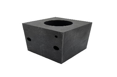
Lithium Battery Negative Electrode Materials and Artificial Graphite Production Process
Lithium batteries mainly consist of four key materials: cathode material, anode material, separator, and electrolyte. The anode material plays a crucial role in storing and releasing energy, significantly influencing the battery’s first-cycle efficiency and cycling performance. It accounts for 6%–10% of the total cost of a lithium battery. Currently, the most widely used anode materials in the market are artificial graphite and natural graphite. Today, we will focus on the production process of artificial graphite.
Artificial Graphite Requires Four Major Processes and Over Ten Sub-Processes
The raw materials for artificial graphite can be categorized into three types:
- Coal-based
- Petroleum-based
- Mixed coal and petroleum-based
Among these, coal-based needle coke, petroleum-based needle coke, and petroleum coke are the most widely used. Generally:
- High-capacity anodes use needle coke as the raw material.
- Standard-capacity anodes use petroleum coke (which is more cost-effective).
- Pitch is used as a binder.
Artificial graphite is produced by crushing, granulating, graphitizing, and sieving the raw materials and binders. While the basic process flow is consistent, the specific preparation methods vary among manufacturers.
Taking Jiangxi Zichen, China’s top artificial graphite supplier, as an example, their production process is as follows:
Here’s an overview of Zichen’s production process:
(1) Pre-Treatment
- Graphite raw materials and pitch are mixed in a ratio of 100: (5–20) depending on the product.
- The mixture is fed into an air-jet mill via a vacuum feeder, grinding 5–10 mm particles down to 5–10 μm.
- A cyclone dust collector recovers ~80% of the particles, while exhaust gases are filtered (≥99% efficiency) using a 0.2 μm filter cloth.
- The entire system operates under negative pressure controlled by a fan.
(2) Granulation
Granulation consists of two steps: pyrolysis and ball milling & sieving.
Pyrolysis Process:
- Intermediate material 1 is loaded into a reactor, purged with N₂, and heated under 2.5 kg pressure.
- It is stirred at 200–300°C for 1–3 hours, then further heated to 400–500°C to form 10–20 mm particles (Intermediate material 2).
- Volatile gases are extracted, condensed into tar, and filtered through activated carbon before release.
Ball Milling & Sieving:
- Intermediate material 2 is vacuum-fed into a ball mill, reducing particles to 6–10 μm.
- The powder is sieved, with undersized particles packaged (Intermediate material 3) and oversized particles re-milled.
- The process is fully enclosed, with dust filtered before emission.
(3) Outsourced Graphitization
- Intermediate material 3 is sent to a carbon plant for graphitization.
(4) Final Ball Milling & Sieving
- Graphitized material is vacuum-transferred to a ball mill for further refinement.
- A 270-mesh sieve separates particles, with qualified material packaged and stored.
From raw coke to the final anode material, the process involves four major steps (crushing, granulation, graphitization, sieving) and over ten sub-processes, making it a lengthy and complex production chain.
Granulation & Graphitization: Key Technical Barriers
Among the four major processes, crushing and sieving are relatively simple. The real technical challenges lie in granulation and graphitization.
Granulation
- Particle size, distribution, and morphology critically impact performance:
- Smaller particles → Better rate capability & cycle life, but lower first-cycle efficiency & compaction density.
- Optimized particle distribution (mixing large and small particles) improves specific capacity.
- Particle shape affects rate performance & low-temperature behavior.
Thus, manufacturers must precisely control particle size and morphology to achieve desired performance.
Graphitization
Graphitization transforms thermodynamically unstable “2D disordered carbon” into ”3D ordered graphite”.
Common Graphitization Furnaces:
- Acheson Furnace
- Prone to uneven heating & thermal stress, leading to cracking.
- Internal Series Furnace
- Issues include graphite dust contamination and poor impurity removal.
Key Optimization Measures:
- Loading Method (horizontal, vertical, staggered, or mixed) and adjusting resistivity spacing.
- Customized Heating/Cooling Curves based on furnace size and product specs.
- Catalytic Graphitization (adding catalysts to enhance graphitization degree).
Additionally, raw material selection (petroleum coke, needle coke, binder) and formulation are crucial proprietary technologies in anode production.
This translation provides a comprehensive and structured English version of the original document, preserving technical details and embedding relevant images for clarity. Let me know if you need any refinements! 🚀
