Abstract
This paper introduces the properties and molding techniques of fluorinated ethylene propylene (FEP) plastics, summarizes common challenges in fluoroplastic lining processes, and proposes targeted solutions.
1. Overview
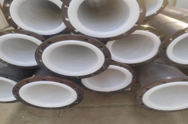
Fluoroplastic-lined valves feature corrosion-resistant FEP coatings on flow surfaces, combining metal structural strength with plastic chemical resistance. This technology aligns with national energy-saving policies and has seen rapid development. Key success factors include:
- Optimal FEP material selection
- Precision lining processes
- Innovative mold design
2. FEP Material Properties
FEP (Fluoroplastic-46) is a copolymer of tetrafluoroethylene (83%) and hexafluoropropylene (17%) with structure:
{−(CF2−CF2)x+CF2−CF}x
CF3
Key Characteristics
| Property | Value |
| Density | 2.14–2.17 g/cm³ |
| Melting Point | 288°C |
| Service Temp | -88–250°C |
| Tensile Strength | 18.6–21.6 MPa |
| Volume Resistivity | 10¹⁷–10¹⁸ Ω·cm |
Advantages:
- Maintains 90% of PTFE’s properties
- Superior processability (injection/compression molding)
- Lower viscosity than PTFE
Challenges:
- Thermal degradation above 400°C
- Electrostatic dust attraction (requires anti-static agents)
3. Processing Techniques
3.1 Processing Parameters
| Method | Temperature | Pressure | Notes |
| Injection | 320–400°C | 29–137 MPa | Mold temp: 200–230°C |
| Compression | 290–370°C | 7 MPa | Cooling to 150–200°C before demolding |
| Extrusion | 315–400°C | 1–18 MPa | L/D ratio >15, compression 3:1 |
3.2 Critical Controls
- Thermal Management: 5°C/min heating rate to prevent cracking
- Tooling Materials: Chromium steel/nitrided alloys for corrosion resistance
- Surface Prep: ISO 8501 St2 standard for substrate cleanliness
4. Valve Lining Process
4.1 Workflow
- Substrate Prep:
- T-slot machining for mechanical interlocking
- Radius all edges (R>2mm internal, R>3mm external)
- Molding:
- Layer thickness: ≥2mm (scales with valve size, see Table 1)
- Degassing cycles: 3–5 times at 300°C
- QC Measures:
- Spark testing (10–15 kV)
- Ultrasonic thickness verification
Table 1: Recommended Lining Thickness
| DN (mm) | Thickness (mm) | |
| 10–50 | ≥2.0 | |
| 65–100 | 2.5 | |
| 125–200 | 3.0 | |
| 300+ | 4.0–5.0 |
5. Quality Assurance
5.1 Defect Prevention
| Issue | Root Cause | Solution |
| Fish-scale marks | Insufficient melt flow | Increase mold temp by 10–15°C |
| Delamination | Poor substrate prep | Add mechanical locking features |
| Cracks | Rapid cooling | Implement staged cooling (50°C/hr) |
5.2 Testing Protocols
- Vacuum Testing: For valves in vacuum service (-0.1 MPa, 30 min)
- Pressure Cycling: 1.5× rated pressure, 1000 cycles
6. Conclusion
FEP-lined valves combine exceptional corrosion resistance (resisting HCl, H₂SO₄, etc.) with structural integrity. Through:
- Material Optimization: Custom FEP formulations
- Process Innovation: Precision compression molding
- Quality Systems: Automated spark testing
Our production data shows:
- 98% pass rate on pressure tests
- 40% longer service life vs. conventional linings