Introduction
Although industrial graphite heat exchangers exhibit outstanding corrosion resistance, long-term operational cycles inevitably lead to the accumulation of water scale, organic residues, silica deposits, and corrosion byproducts. Every 1 mm increase in fouling thickness can reduce heat transfer efficiency by 10% to 15%, ultimately causing fluid channel blockages or premature equipment failure.
Based on two decades of manufacturing and field engineering experience, this operational guide outlines standardized cleaning strategies, chemical agent selection, safety red lines, and preventive maintenance protocols to help plant engineers extend equipment service life and minimize downtime.
Part I: Necessity of Cleaning & Inspection Triggers
Equipment management teams should schedule immediate shutdown inspections and cleaning routines upon encountering any of the following operational anomalies:
-
Significant Drop in Thermal Efficiency: Outlet temperatures fail to reach design specifications under normal utility flow rates.
-
Abnormal Differential Pressure Spikes: Marked pressure drop increases between inlet and outlet nozzles.
-
Fluid Flow Restrictions & Noise: Irregular internal acoustic profiles indicating localized channel constriction.
-
Visual Fouling During Inspection: Scale or sludge build-up observed on accessible heat transfer surfaces during routine checkups.
Part II: Pre-Cleaning Preparation & Safety Protocols
-
System Shutdown & Isolation: Close upstream and downstream valves to isolate the heat exchanger completely from the active chemical process loop.
-
Purging & Displacement: Drain all internal process fluids and perform 2 to 3 displacement flushes using clean water or inert gas (such as nitrogen) to eliminate toxic, flammable, or hazardous residues.
-
Fouling Sampling & Analysis: Collect deposit samples for laboratory testing (e.g., chemical titration or XRD analysis) to determine whether the deposit is inorganic water scale, organic oil/sludge, or silica scale.
-
Personal Protective Equipment (PPE): Operators must wear acid-resistant gloves, protective goggles, and full chemical suits. Maintain continuous forced ventilation and deploy gas detectors to monitor hazardous vapors.
Part III: Core Cleaning Methodologies
Cleaning operations must adhere to the core engineering sequence: “Physical cleaning first, chemical cleaning supplementary, and combined cleaning when necessary.”
1. Physical Cleaning Methods (No Chemical Residues; For Loose/Light Deposits)
-
High-Pressure Water Jetting: Maintain jetting pressure strictly between 10 to 25 MPa (never exceed 25 MPa to prevent mechanical damage to graphite walls). Position nozzles 30 to 50 cm from the surface, directing the water flow parallel to heat transfer surfaces rather than perpendicular.
-
Soft Mechanical & Online Cleaning: For tube-side cleaning, utilize sponge rubber balls (with diameters 10% to 15% larger than tube inner diameters) or nylon brushes driven by circulating water. Never use metallic tools for scraping.
-
Gas-Liquid Pulse Cleaning: Alternate compressed air pulses (0.5 to 1.0 MPa) with clean water flushes to strip soft deposits via impact energy, ideal for narrow tube bundles.
⚠️ Caution Regarding Severe Blockages (Spiral Drill Method):
Mechanical spiral drilling should only be deployed as a last resort when heat exchange passages are completely plugged and impervious to liquid penetration. This procedure requires experienced technicians operating low-rpm drills with gradual feed rates. Because mechanical drilling carries an inherent risk of graphite wall damage, evaluate feasibility with technical specialists prior to execution.
2. Chemical Cleaning Methods (For Stubborn Deposits; Strict Parameter Control)
Different deposit compositions require specific chemical formulations and operating conditions:
| Deposit Type | Recommended Chemical Agent | Concentration & Temperature | Circulation Time |
|---|---|---|---|
| Water Scale (Carbonates) | Hydrochloric Acid (with 0.5%–1% corrosion inhibitor) | 5%–15% HCl at 40°C–60°C | 1–4 Hours |
| Light Scale / Gentle Cleaning | Citric Acid or EDTA Disodium Salt | 3%–5% Citric Acid OR 2%–5% EDTA (pH 8–10) | 2–4 Hours |
| Oil / Organic Sludge | Sodium Hydroxide (NaOH) OR Surfactants | 2%–5% NaOH at 50°C–70°C OR 0.5%–1% SDBS | 3–5 Hours |
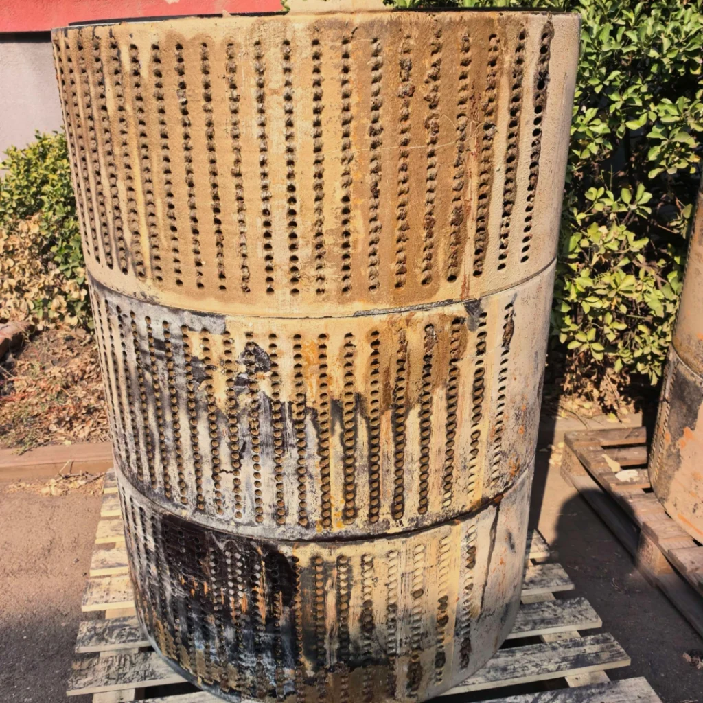
Note for Block-Type Exchangers: Cylindrical graphite blocks can be disassembled and soaked directly in the recommended cleaning solutions. As long as strong oxidizing acids (such as nitric acid) are avoided, chemical soaking will not degrade impregnated graphite blocks.
Standard Chemical Cleaning Sequence:
-
Pre-Flushing: Flush channels with clean water to clear loose debris.
-
Chemical Circulation: Circulate the chosen reagent within specified temperature and concentration limits.
-
Neutralization: Neutralize acid flushes with dilute sodium carbonate, or alkaline flushes with weak acid solutions.
-
Deionized Water Rinsing: Rinse until effluent water reaches neutral pH (7.0 to 8.0).
-
Passivation: Circulate 0.5%–1.0% sodium nitrite for 1 to 2 hours to protect exposed metallic shell components.
3. Combined Cleaning Methods (For Complex Mixed Deposits)
-
Oil + Water Scale: Apply surfactant degreasing first, follow with acid descaling, and finalize with deionized water rinsing.
-
Heavy Hard Scale: Perform chemical soaking to soften deposit matrices, followed by high-pressure water jetting.
Part IV: Post-Cleaning Inspection & Testing
-
Visual & Structural Inspection: Inspect graphite units for microcracks, joint debonding, or material degradation.
-
Pressure & Leakage Testing: Conduct hydrostatic testing at 1.5 times the operating pressure or pneumatic testing at 0.2 to 0.3 MPa to verify flange and nozzle integrity.
-
Residue Testing: Verify flush water with pH test paper to confirm values between 6.0 and 8.0, ensuring zero chemical reagent carryover.
-
Drying Protocol: Allow natural air drying or warm air drying at temperatures ≤ 60°C (never use high-temperature baking to prevent thermal cracking).
Part V: Preventive Maintenance & Service Life Extension
-
Anti-Shock Operations: Open and close control valves slowly during startup and shutdown to prevent water hammer. Maintain inlet/outlet temperature differentials below 30°C to prevent thermal stress cracking.
-
Filtration & Blowdown: Install upstream strainers to intercept large suspended solids, and regularly flush out metallic impurities and crystallites.
-
Sealing Maintenance: Periodically inspect gaskets and flanges. Replace degraded gaskets with original-factory seals promptly; never disassemble components while under pressure.
-
Idle Preservation: Clean, thoroughly dry, and seal units before long-term storage. Store in a protected environment away from heavy loads and physical impacts.
-
Cleaning Intervals: Schedule routine cleaning every 3 to 6 months under continuous operating conditions, or inspect every 2 to 3 months for highly corrosive or hard-water systems.
Part VI: Operational Red Lines & Critical Restrictions
-
Prohibit Strong Oxidizing Agents: Never use concentrated nitric acid, concentrated sulfuric acid, potassium permanganate, or hydrogen peroxide, which cause severe graphite matrix oxidation.
-
Avoid Long-Term Strong Alkali Exposure: Standard phenolic-impregnated graphite units suffer degradation under prolonged strong alkali exposure.
-
Exercise Extreme Caution with Fluorine-Based Cleaners: Fluoride ions can attack certain binders. High-density graphitized materials impregnated with phenolic resin and heat-treated above 150°C can withstand fluoride-based silica cleaning without quality loss. For other material grades or processing histories, consult the manufacturer prior to use.
-
Control Temperature Limits: Never allow cleaning solution temperatures to exceed 60°C to prevent thermal stress cracking and resin degradation.
-
Prohibit Metallic Scraping: Never utilize steel wire brushes or metal scrapers on graphite surfaces.
-
Effluent Treatment: Neutralize all cleaning waste fluids to a pH of 6.0 to 9.0 and comply with local environmental discharge standards prior to disposal.
Conclusion
Effective cleaning and maintenance of graphite heat exchangers require a disciplined approach balancing mechanical safety with chemical compatibility. By adhering to non-destructive physical cleaning methods, precise chemical agent parameters, and strict operational red lines, processing plants can maintain peak thermal efficiency while extending equipment service life.
For specialized technical consultation regarding corrosion-resistant equipment selection, custom graphite block configurations, or field maintenance services, please contact the engineering team at Benecustcep for Graphite Heat Exchanger.