
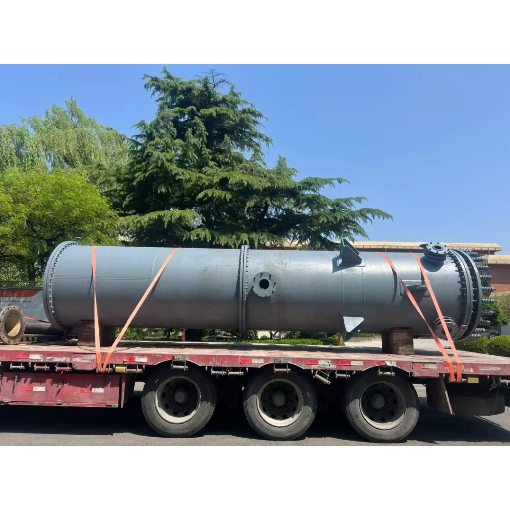
Introduction
Graphite heat exchangers are widely utilized in highly corrosive environments across the chlor-alkali hydrochloric acid industry, titanium dioxide sulfuric acid processes, phosphoric acid production, fluorochemical hydrogen fluoride and methyl chloride processes, as well as pharmaceuticals, agrochemicals, and halogenated acid sectors. They seamlessly adapt to various concentrations of hydrochloric acid, sulfuric acid below 70%, phosphoric acid, and diverse corrosive salt solutions.
Based on 20 years of design, manufacturing, and standardization expertise in graphite equipment, this article aims to provide structured diagnostic strategies for field engineers. Due to variations in actual operating conditions, this content serves as professional reference guidance rather than mandatory national or international standards. Please apply discretion based on on-site conditions.
As a brittle, impervious material, industrial graphite is primarily categorized into two mainstream structural types: block-type (block-hole) and shell-and-tube. Their structural vulnerabilities and failure progression pathways differ significantly. Under long-term corrosion and cyclic operating conditions, these units gradually suffer from performance degradation and media leakage. Many hidden damages are difficult to detect during routine inspections; once manifested, they can lead to unplanned shutdowns and severe containment risks. By examining the differential structural characteristics of both types, this article classifies failure modes, outlines field diagnostic workflows, and establishes troubleshooting logic and repair principles for root-cause analysis, remaining life prediction, and maintenance optimization.
Overview: Core Characteristics Comparison of Two Types of Graphite Heat Exchangers
| Comparison Dimension | Shell-and-Tube Graphite Heat Exchanger | Block-Type (Cylindrical) Graphite Heat Exchanger |
|---|---|---|
| Core Structure | Shell, graphite tubesheet, and numerous parallel graphite heat exchange tubes | Stacked impregnated graphite blocks with internal crisscross drilled holes |
| Weakest Points | Graphite tube body, tube-to-tubesheet bonding interface | Cross-channel walls inside blocks, block-to-block sealing gaskets |
| Primary Failure Manifestations | Tube bundle fracture, bonding joint cracking, tube-end leakage | Internal channel breakdown/cross-contamination, inter-block flange/gasket external leakage |
| Thermal/Pressure Shock Resistance | Relatively weak (vulnerable to thermal shock and water hammer) | Relatively strong (compact structure, superior pressure and shock resistance compared to tubular types) |
Part I: Specialized Guide for Shell-and-Tube Graphite Heat Exchangers
Shell-and-tube heat exchangers consist of a shell, tubesheets, and numerous parallel graphite heat exchange tubes. Their core weak points concentrate on the graphite tube bodies and the bonding interfaces between the graphite tubes and tubesheets. Click for more information about tube-Type Graphite Heat Exchangers.
1. Core Failure Modes and Root Cause Analysis
Graphite Tube Bursting, Pulling, and Brittle Fracture
-
Mechanical Damage: Microcracks generated by collisions during transportation and installation; pipeline system vibrations or pump pulse transmissions leading to fatigue fracture.
-
Steam Erosion and Cavitation: Absence of a baffle plate at the shell-side steam/material inlet, allowing high-temperature, high-velocity fluid to directly scour the inlet section of the graphite tubes, resulting in localized wall thinning and rapid cracking.
-
Thermal Stress and Low-Temperature Embrittlement: Rapid cooling and heating causing cracking due to the thermal expansion coefficient mismatch between the graphite tubes and the adhesive (such as phenolic resin); when ambient temperature is < 0°C, the impact toughness of the graphite material drops, making it extremely prone to low-temperature brittle fracture.
-
Water Hammer Impact: Pump startup/shutdown or rapid valve opening/closing generating transient pressures > 1.5 MPa (water hammer effect), which directly shatters the brittle tube bundles.
Tubesheet and Tube-Joint Bonding/Impregnation Layer Failure
-
Chemical Media Degradation: Long-term contact with strong oxidizing acids (e.g., nitric acid, concentrated sulfuric acid, sodium hypochlorite) or strong alkalis (e.g., sodium hydroxide) causes chemical degradation and swelling of traditional phenolic resin adhesives and impregnation layers.
-
Microscopic Characteristics: The pore structure of the graphite resin is corroded away, losing its original resin gloss; completely resin-free surfaces exhibit graphite powderization/loosening characteristics, leading to a complete loss of anti-seepage capability.
-
Assembly and Thermal Stress: Excessive tube straightness deviation or tubesheet hole pitch tolerance causes individual heat exchange tubes to bear long-term extra tensile stress; during operation, if the temperature difference between the shell and tube bundle is excessive and expansion joints fail, tube-joint bonding areas are easily torn apart.
-
Sealing Structure Innovation: To address these pain points, Benecustcep has proposed a sealing structure utilizing O-ring seals to ensure the tight sealing between tubes and tubesheets, successfully resolving bonding cracking issues caused by thermal expansion and mechanical shock. This structure effectively adapts to severe bonding cracking challenges under evaporation, high-temperature, and large-area operating conditions. (For detailed technical information, feel free to contact us via email.)
Connection Sealing Leakage
-
Water Leakage Between Head and Top/Bottom Plates: Excessive external piping stress pulling on the head, resulting in poor gasket sealing or misaligned gaskets.
-
Bolt Pre-tightening Force Relaxation: Frequent thermal cycling causing thermal creep in metal bolts, leading to pre-tightening force decay and subsequent leakage.
2. On-Site Diagnostics and Location Methods
-
Hydrostatic Tube-Finding Method: Fill the tube side with water to a level higher than the upper tubesheet, and quickly open the condensate drain valve. When a vortex appears on the upper tubesheet water surface, plug that upper port with a stopper and close the valve; repeating this process accurately pinpoints broken graphite tubes.
-
Pressure Testing and Holding Inspection: During pressure testing, damaged tubes will exhibit vortices or water seepage on the tubesheet surface. Maintain a pneumatic/hydrostatic pressure of 0.3~0.4 MPa for 30 minutes to inspect for microcracks.
-
Non-Destructive Testing: Regularly use ultrasonic testing or eddy current testing to inspect internal tube wall microcracks and wall-thinning conditions.
3. Maintenance and Countermeasures
Single or Few Tube Damages (Plugging and Replacements)
-
Plugging Method: Use graphite plugs matching the tubesheet hole diameter, combined with corrosion-resistant adhesive, to seal both ends of the damaged tube.
⚠️ Engineering Warning and Calculation Reference:
Typically, graphite heat exchangers reserve about 15% design margin in heat exchange area. In actual operation, the cumulative plugged tube count in a single heat exchanger should ideally be controlled within 30% to 40% of the total tube count.
Plugged < 15%: Generally maintains original design heat exchange performance.
Plugged 15% ~ 30%: System heat exchange capacity begins to drop; performance can be compensated by moderately increasing cooling media flow or temperature difference.
Plugged > 30% ~ 40%: Severe loss of heat exchange area, coupled with sharply increased fluid velocity and resistance in active tubes, which easily triggers erosion-corrosion and water hammer. At this stage, the entire tube bundle must be replaced or sent back to the factory for re-tubing.
-
Tube Replacement Method: Open up the local bonding layer, extract the old tube, replace it with a new one, and re-apply adhesive and cure.
-
Large-Scale Bonding Failure: Requires returning to the factory or utilizing specialized mechanical methods to cut open bonding surfaces, clean, re-machine, re-impregnate, and re-bond.
-
System Protection Optimization: Install slow-opening electric valves in pipelines (to prevent water hammer); implement DCS/PLC automated temperature control (limiting heating rates to < 5°C/min); thoroughly drain accumulated liquid and ensure freeze protection during shutdowns in cold regions; install plastic-lined or titanium anti-erosion protection plates at steam inlets.
Part II: Specialized Guide for Block-Type (Cylindrical) Graphite Heat Exchangers
Block-type heat exchangers consist of multiple stacked impregnated graphite blocks with internal crisscross process and cooling holes. Their core weak points concentrate on the internal cross-channel walls of the graphite blocks and inter-block sealing gaskets.Click for more information about Block-Type Graphite Heat Exchangers.
1. Core Failure Modes and Root Cause Analysis
Internal Channel Cross-Contamination (Two-Phase Media Inter-Leakage)
-
Material and Manufacturing Defects: Uneven graphite impregnation, local porosity; or drilling deviation during deep-hole machining, resulting in inter-channel wall thicknesses below safe allowable limits.
-
Impregnation Resin Chemical Failure: Under strong oxidizing agents (nitric acid, concentrated sulfuric acid) or strong alkali (sodium hydroxide) conditions, impregnation resin swells, degrades, or even carbonizes.
-
Microscopic Characteristics: The pore structure of the graphite resin inside channel walls disappears, losing its luster; completely resin-free surfaces present graphite powderization. Effective wall thickness drastically reduces, leading to direct channel wall breakdown and cross-contamination under operating pressure.
-
Thermal Shock and Crystallization Crushing: Localized rapid cooling/heating generating thermal stress cracks; material crystallization continuously accumulating at cross-hole intersections, where crystal volume expansion crushes channel walls and causes physical cracking.Failure of this type of graphite block usually occurs in individual units rather than all heat exchange blocks. Identical graphite blocks can be custom-made for replacement and repair, which is more cost-effective than replacing the entire graphite heat exchanger. Contact the Benecustcep team if you have requirements for custom replacement graphite blocks.
Inter-Block Sealing Gasket Leakage (High-Frequency Failure)
-
Gasket Selection/Aging: Gasket materials (such as regular rubber, asbestos, etc.) lacking resistance to strong acids/alkalis or high temperatures, resulting in swelling, hardening, and powdering decay.
-
Pre-load Imbalance: Uneven unilateral force applied during the tightening of external spring tie rods or bolts, leading to gasket misalignment or localized sealing specific pressure deficiency.
-
Secondary Corrosion Damage: Micro-leaks from gaskets remaining undetected, allowing acid mist/strong alkali to spread and severely corrode external metal shells, anti-corrosion coatings, and fastening bolts.
Head and Bottom Plate Cracking
-
Massive thermal expansion/contraction stresses from external piping acting directly on graphite heads due to the lack of flexible expansion joints; or damage caused by installation/transportation impacts.
2. On-Site Diagnostics and Inspection Methods
-
Segmented Isolation Independent Pressure Testing: Blind off the tube side and shell side separately, and conduct independent pressure tests (hydraulic/pneumatic). Through graded pressure holding, quickly differentiate between “inter-block gasket external leakage” and “internal graphite block channel breakdown/cross-contamination.”
-
Operating Parameter and Media Monitoring: Monitor output purity and abnormal pressure fluctuations; regularly sample pH values or specific ion concentrations (such as sudden chloride ion spikes) in cooling water/heating steam condensate to preliminarily detect early micro-leaks.
-
Disassembly Endoscopy and Visual Inspection: Inspect equipment shell joints for acid mist or salt traces; after disassembling graphite blocks, use an endoscope to check internal channel walls for whitening, powdering, or resin loss.
3. Maintenance and Countermeasures
-
Gasket Leakage Treatment: Disassemble the clamping structure and thoroughly clean sealing surfaces. Replace with matching gaskets based on media selection (recommended ePTFE-enveloped or expanded PTFE gaskets), and tighten bolts strictly following a diagonal, crisscross, multi-step pattern using a torque wrench.
-
Graphite Block Repair and Replacement:
-
Micro-seepage/Localized Damage: Can undergo annealing cleaning followed by local re-impregnation and resin curing repair.
-
Large-Scale Powderization/Breakdown: Damage is irreversible; the individual graphite heat exchange block of the same specifications must be directly replaced.
-
-
Fastener Corrosion Countermeasures: For corroded metal tie-rod bolts, replace them with bolts of the exact same material grade and specification as the original design.
Part III: Hidden Failures and Monitoring Common to Both Equipment Types
Aside from sudden leaks and burst tubes, both equipment types face “performance degradation without external visible leakage,” requiring established periodic monitoring mechanisms:
1. Heat Exchange Performance Degradation (Increased Thermal Resistance & Decreased Thermal Conductivity)
-
Failure Phenomenon: High condensed output temperature, increased steam consumption, or failure to meet designed heat exchange capacity.
-
Monitoring and Judgment: Real-time monitoring of inlet/outlet temperature differences and flow rates to calculate the overall heat transfer coefficient (K value). If fouling (scaling, material crystallization) is ruled out and the K value still drops sharply, it is usually because the graphite matrix has undergone “thermal aging” or microscopic oxidation under long-term high-temperature or strong oxidizing environments, resulting in deteriorated thermal conductivity and increased internal thermal resistance of the material.
2. Wall Thickness and Structural Dimension Decay
-
Judgment Indicators: Wall thickness of heat exchange tubes or block holes gradually thins due to high-velocity fluid scouring, chemical corrosion, or particle abrasion.
-
Warning Threshold: Wall thickness reduction exceeding 10% of the initial value constitutes severe wear; if localized pitting, powdering, or corrosion spots are evident, the equipment must be listed for priority monitoring to avoid sudden breakthrough during pressure fluctuations.
Part IV: Full Lifecycle Prevention and Intelligent Maintenance
Standardized Startup/Shutdown Operations:
-
Strictly control temperature and pressure change rates (recommended heating rate < 5°C/min).
-
In cold seasons or during long-term shutdowns, freeze-drain valves must be opened to completely purge internal trapped liquid.
-
Prior to startup, shell-side and tube-side gases and condensates must be fully purged to prevent cavitation and water hammer.
Strictly Enforce Design Limits:
-
Maintain block-type pressures ≤ 1.0 MPa, temperatures ≤ 280°C; keep extruded shell-and-tube pressures ≤ 0.3 MPa, temperatures ≤ 150°C. For specific details, please refer to the engineering drawings and final documentation.
Quantitative Torque Management:
-
Flanges and block-type fastening bolts must be tightened using torque wrenches or hydraulic wrenches. Apply cross-tightening in three stages (30%, 60%, 100%) to eliminate eccentric loads and structural damage to graphite components caused by guesswork.
Precise Material Selection (Resins and Gaskets):
-
Strong Oxidizing Acids (Nitric Acid, Concentrated Sulfuric Acid): Select special fluororesin-impregnated graphite.
-
Strong Alkaline Conditions (NaOH): Select furan resin-impregnated graphite (strictly avoid standard phenolic resins which lack alkali resistance).
-
Sealing Gaskets: Recommended expanded PTFE (ePTFE) gaskets or flexible graphite composite gaskets tailored to the media, eliminating ordinary rubber and asbestos gaskets.
Establish Equipment Full Lifecycle Records:
-
Graphite Main Body: In clean service, designed service life of graphite blocks is approximately 8~10 years; severe corrosion/crystallization/high-scouring conditions typically shorten life to 3~5 years.
-
Sealing Components: Standard life is 2~3 years; high-temperature or highly corrosive conditions warrant preventative replacement every 1~1.5 years.
-
Periodic Factory Maintenance Mechanism: For block-type equipment, it is recommended to contact the manufacturer after 3~5 years of operation for overall disassembly, cleaning, annealing re-impregnation, and re-hydrostatic testing to significantly extend comprehensive service life.
Standardized Cleaning: Prohibit high-pressure direct jetting or hard-tool scraping on graphite surfaces to safeguard impregnation layers.
Part V: Field Diagnosis Anti-Pitfall Checklist
-
Rising pressure drop does not automatically mean crystallization clogging; resin swelling, bore constriction, or flow maldistribution can also cause pressure spikes.
-
Acid mist around flanges is not necessarily a flange gasket leak; it can stem from graphite matrix micro-permeation or nozzle micro-cracks seeping along gaps.
-
Decreased thermal performance without external leaks should first prompt checks for flow maldistribution and plugging rather than assuming a base material failure.
-
Pressure decay during hold tests requires differentiating three scenarios: external leakage, internal cross-leakage, or shell lining damage.
-
Tubesheet adhesive aging leaks are easily misdiagnosed as fractured heat exchange tubes; always perform segregated pressure tests to confirm.
-
Check nozzle roots and extended exposed nozzles for legacy mechanical damage or micro-crack propagation originating from transport and installation.
Conclusion
The core of on-site maintenance for graphite heat exchangers lies in “Pre-vention of Water Hammer, Mid-vention of Corrosion, Post-vention of Eccentric Stress“:
-
Preventing Water Hammer: Eliminate water hammer and thermal shock through slow valve opening and proper venting.
-
Preventing Corrosion: Match correct impregnating resins (phenolic/furan/fluororesin) and gaskets to resist media-induced powdering erosion of bonding layers and graphite pores.
-
Preventing Eccentric Stress: Apply rated and uniform bolt torques to avoid tearing brittle graphite matrices due to uneven stress.
Graphite heat exchanger failure stems from coupled factors including material properties, assembly stresses, media corrosion, and process operations. Core risks for shell-and-tube units involve thermal expansion mismatches at tubesheet bonds and mechanical tube bundle damage; core risks for block units relate to drilled wall thickness defects and inter-block gasket aging. Field diagnosis must adhere to the sequence of “process analysis first, physical leak testing second, and disassembly validation last” to prescribe targeted solutions and avoid blind full-unit replacements.